The Structured Programming approach to CAD
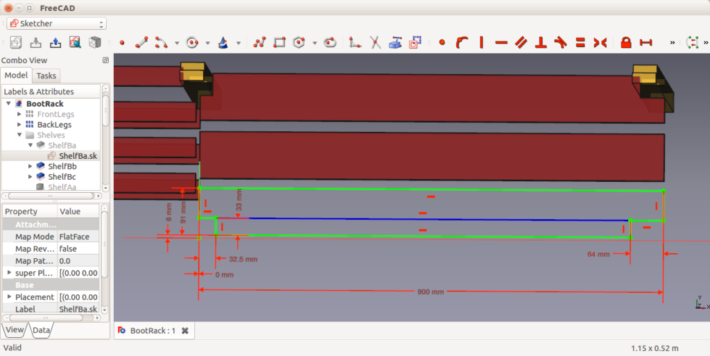
I want my CAD software to remember how my model is constructed. If a shape is repeated in three places, I want to be able to modify that shape in one place and have the change propagated to all three places at once. If a face is rectangular, I want to know that its edges will remain parallel when I adjust its width. If each shelf in my boot rack is 18 mm thick, I want its thickness to stay at 18 mm and not reduce by 10% when I decrease the overall height of the rack from 1000 to 900 mm.
I don’t want my CAD software to remember only the final, external shape, as if it is the solid block of plastic that was printed by a 3D printer, and to allow me to alter it only by cutting a bit off or adding a bit on to that external shape one face at a time, like a sculptor using a chisel (and glue).
For me the ability to use structured design techniques, somewhat analogous to the structured programming methodology, is a key requirement for computer-aided design.
Compound Objects
We must be able to group objects together and treat the group as a single object for many purposes.
Constructive Solid Geometry operations such as union (called “fusion” in FreeCAD) and difference (“cut”) make a more complex solid shape from two or more simpler solid shapes.
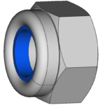 A compound object is more than just a union of shapes. For one thing, it needs to allow shapes with different properties, such as a steel nut with a plastic insert (a “Nyloc” nut).
I need to look more closely at DeepSOIC’s Non-PartDesign Body container proposal which looks like it is on the right track for this.
Cloning
I want to design a shape and then insert more than one copy of it. Each wooden shelf of my boot rack is made of three or five parallel strips, which I model as cuboids initially. Later I decide to smooth their upper edges. To do this, I want all the strips to be based on a single template, and I want to modify that template so that the upper two corners are rounded. I don’t want to have to manually select each of the 52 individual edges in turn in order to apply a 4 mm radius.
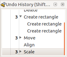
Basic repetition like this requires the ability to clone a compound object. FreeCAD has the “Part Clone” operation which does this. However, a complication arises when I later modify the original. Many modifications, e.g. “fillet”, are done by wrapping the object with a transformed version of itself. The clones remain clones of the original object and so don’t reflect that modification. One existing way to overcome this is to wrap the object in a container such as “PartDesign Body” (though it has restrictions) and clone the container; then the fillet can be made inside the container and so is reflected by the clones. Another possible design could be that the “Fillet” tool offers to update the clones to point to the new Fillet object instead of the original if the user so chooses.
We need to think clearly about the notion of “the original”. If my table has four legs, I might designate one as the original and the other three as clones. Then if I want to modify them all in the same way I need to easily find the original, and make changes to it in such a way that the changes are reflected in the clones. Alternatively I could make an abstract (hidden) original, and make four clones of that. The abstract, hidden “original” might then be called a template. If I want to make a unique modification on each leg, this approach might be easier to work with, because the difference between the template and the first leg is completely clear, and I can easily choose whether I’m making a change to the template or to a particular instance.
One aspect to using clones is the importance of a local coordinate system that is used in the definition of the original object, since the cloned instances will be placed at different positions within the global coordinate system.
Lattices
Going beyond manually placed clones, it is useful to be able to place a regular array or grid or lattice of clones. FreeCAD provides a simple and very limited array operation.
I am pleased to see that DeepSOIC has been working on a Lattice Workbench for FreeCAD. This looks like it is done the Right Way, a vast improvement over the simple array operation.
We could say that using lattices is somewhat analogous to looping in a sequential programming language: for x in 0, 1, 2, 3: for z in 0, 1, 2: shelf(x * 900, y=0, z * 450 + 100);
Parametric Templates
Notice how a CAD program will usually assume that several simple shapes such as a cuboid and a cylinder are fundamental building blocks, and provide parametric templates for them. That is to say, if I use the provided cuboid tool instead of building one out of six separate faces, then FreeCAD will ensure all the angles remain right angles while allowing me to adjust the length and width and height.
That is all very well but the same principle must also be available for more complex shapes. The width of some strips of my shelves is different from others, so I want the template to be parametric. In this case:
- a roughly cuboidal shape
- 18 mm thick
- variable width and length
- two of the edges are rounded to a 4 mm radius
And then I want to place one instance at x=0, y=0 with length=900, width=46; and another instance at x=0, y=60 with length=900, width=80; and so on.
The width and length are parameters to be specified on each instantiation (in addition to the placement): that is what makes this a parametric template.
So I need my CAD software to let me define parametric templates for all the shapes I want to use. That is analogous to writing a function in structured programming, and calling the function several times with different parameters.
- Is there a different professional terminology for what I’m calling “parametric templates” here?
Part Library
A Part Library facility will make it easy to manage templates: to organize and refer to the templates within one model, and to import parts into the model from a shared library of parts, and to create such a library.
- There is a project called FreeCAD-library. It provides some shapes that may be copied. They are not “parametric templates” in the sense above — for example. There are no associated software enhancements to help with using them.
Refactoring
It must be easy to redefine the way the model is built while preserving the same result.
By refactoring, I mean the ability to replace one definition of an object (or any kind of data in the model) with another definition that produces the same or a similar result. If any other node in the model depended on the node that implemented the old definition, it shall henceforth depend instead on the new one.
Examples:
- exchange the order of commutative transforms: e.g. change an array of unions to a union of arrays
- move/rotate/scale a local coordinate system: apply the opposite transformation to the placement of each instance so there is no net change
- a template specifies the material “wood”; change the template to not specify a material, and change all instances that didn’t override it to specify material “wood”
- replace a stored transform with its current result (additional possibilities: freeze its result & inactivate but remember the transform; freeze the result & ensure the transform continues to give that result)
- replace a 2D object with a sketch of itself, or vice versa
- break any predefined object into its primitive parts along with the relevant constraints
- replace constraints with equivalent ones: e.g. length & two angle constraints with two length constraints and one angle, defining a triangle
For any refactoring, the opposite refactoring should be available too, to the greatest extent possible.
Extrusion: 2D Sketches and 1D Profiles
Making a 2D sketch and extruding it along the third dimension is a powerful and convenient way of designing 3D shapes. In FreeCAD the Sketcher provides parametric or “constraint-based” 2D drawing that can be used as the basis for extrusion, as an alternative to using a normal 2D shape. (Indeed, the documentation suggests the Sketcher was only intended to be used for this purpose.)
Extruding a 2D face in FreeCAD makes a single solid of uniform thickness. I want a more general extrusion in which the 1D thickness profile is analogous to the 2D profile. I want to extrude my sketch not just in a single homogeneous span but in several segments (example: z=0 to 6 mm; gap; z=12 to 18 mm) to create several solid layers with or without gaps between them.
I want to store a 2D sketch as a template and use it in multiple places with different 1D extrusion profiles. I want to store a 1D extrusion profile as a template and use it in multiple places with different 2D sketches. An extrusion profile can thus serve as a specification for a composite sheet material.
A 1D profile should be able to be parametric (constraint-based), just as a 2D sketch can.
I want to be able to attach properties such as material and colour to the faces in my 2D sketch, and also to the segments in my 1D profile (z=0 to 6 material=plywood; gap; z=12 to 18 material unspecified).
Property specifications should be defaultable (“if not already specified then this”) and overrideable, so that I can choose to specify the material either in the 1D extrusion or in the 2D sketch or by a more complex combination of both.
- 2D sketch — specifies 2D faces
- 1D profile — specifies 1D segments
- both can be parametric (constraint-based)
- both can be multi-segment
Stored vs. Immediate Transforms
Mirroring, rotation, array — these are parametric ways of defining one part of the model in terms of a transformation of another part.
When a transformation is stored as a transform operator node in the model, then the parameters defining the transform (axis for mirroring, centre and angle(s) for rotation, etc.) can be changed later and the resulting object will be recalculated, or the base object can be changed later and the resulting object will be recalculated to reflect that base object. I will call this way of modelling the stored parametric transform.
The other possibility when applying a transform operator is to store only the resulting object and not the transform that was used. I’ll call that the immediate way of applying a transform.
Both behaviours are useful and both should be available for every kind of transform. The most likely wanted behaviour may well vary depending on the operator and other factors, but what we don’t want is an arbitrary mixture of behaviours, some operators creating a stored transform and others applying their effect immediately.
In FreeCAD today there does seem to be an arbitrary mixture.
In my ideal CAD program there would be a UI to change any operation from parametric to empirical, by removing the transform operator from the model and placing the result instead. This is somewhat analogous to removing a constraint: afterwards, modifying the base object will no longer affect the object created by the transform.
A more advanced UI should also provide ways to convert from empirical to parametric. This is tricky: if B is supposed to be a transformed version of A, then does B in fact differ from A only in respect of one simple transform? Should the UI try to guess the transform or must the user specify it? What if B differs arbitrarily from A? How do we even compare the objects objectively (given they may look the same but be constructed differently, for instance)?
Uniform Hierarchical Modelling
We need to be able to build any further geometry on any calculated geometry. For example, after extruding a flat face to produce a polyhedron, it must then be possible to use any face of that calculated polyhedron as the base for a further extrusion. To achieve this, every calculated result should be presented in the model as standard geometry and not only as a special kind of object whose result doesn’t act like standard geometry.
Requirements:
- standard objects are composed of standard geometry
- when I use the built in Rectangle tool, I can select two of its edges and build further geometry on them
- transform result is standard geometry
- when the result of a transform operator is a rectangle, I can select two of its edges and build further geometry on them
- sketch result is standard geometry plus constraints
- I can build further on two lines of a sketch
It should always be possible to:
- transform an object in place: that is, replace it with a transformed version of itself, either a stored transform or an immediately applied transform
- replace an object with a transformed version of another (especially interesting when the result is similar to the old object)