Open-source Scanning

In the last few years I have been scanning most of the printed documents I receive. Bank statements, important receipts, event tickets to keep as souvenirs. I also from time to time scan batches of old documents such as my University notes.

I envision a free software solution that makes it easy.

SimpleScan, Pdf-Shuffler, gscan2pdf

The default solution for scanning documents on Ubuntu is not great. SimpleScan is very useful, and I have used it to scan the vast majority of my paper documents for the last few years. It has some good qualities, but at the same time is annoyingly crude. Main omissions:

  • OCR support.
  • Load a previously saved document and scan more pages into it. (For correcting mistakes.)
  • Scan a stack of pages and then divide them into separate documents. (For speed.)
  • Undo.
  • Automatic page size detection, rotation (right angles or de-skew), blank page skipping, and so on.
  • Basic UI usability (e.g. selecting and re-ordering pages doesn’t work well; forgets the crop size and position).
  • Generally stable but some serious bugs, e.g. deleting one page while another is scanning leads to data corruption.

To add more pages to a previously saved PDF document, I use PDF-Shuffler. It too is useful but crude, lacking:

  • Undo.
  • Basic UI usability (e.g. multiple selection of pages doesn’t work properly; doesn’t remember its own window position and size; doesn’t provide a dead-simple way to save the result back to the same file).

I tried gscan2pdf mainly for its OCR promise (see below), but I also liked that it can do automatic corrections such as de-skew. However, I found those features nearly impossible to configure because they are basically undocumented and presented as meaningless numbers with no clue how to choose useful values or how they interact.

On the plus side, gscan2pdf scans from my HP Photosmart C7280 all-in-one device at about twice the speed SimpleScan does, keeping up with the scanner’s speed, while SimpleScan makes the scanner pause several times per page. I don’t know if this is because it is using different scan settings and receiving less data, or because it is more efficient at receiving the data.

OCR

Most of the documents for which I expect OCR to work were printed by a computer in a nice regular clean typeface. In this century it seems ridiculous that the computer still can’t read what it wrote.

For OCR I have tried gscan2pdf, with both Tesseract and Cuneiform OCR engines. The OCR results I have obtained have been decidedly poor, good enough for generating an index of words found in the document but not good enough to want to display the result.

By contrast, the OCR performed by what I understand is a version of Abbyy FineReader embedded in my Fujitsu ScanSnap N1800 scanner gives excellent results, almost perfectly transcribing most printed pages. A notable exception is it swaps bold for italic and italic for bold. It only OCR’s one page a minute, and the scanner’s UI software is dreadful, but this does show what can be achieved by good OCR software.

Free Software Improvements

What’s needed for a good free software solution? Two main things:

  • Decent basic UI
  • OCR that just works

For the former, adding Undo to a combination of SimpleScan and PDF-Shuffler would form a good basis in terms of features and rough UI design, with maybe some ideas from gscan2pdf as well. This seems a run-of-the-mill software design and programming task.

For the OCR, I expect some intensive work is needed. It need not be totally out of reach for a group of keen volunteers, but might be more likely to happen if there were some investment by one of the big players such as Canonical, IBM or Google (who have improved Tesseract a lot but it’s not a complete OCR solution).

And then could come enhancements such as:

  • Automatic rotation, de-skew, blank page skip, cropping, …
  • Detecting a small palette of colours (often black, white and one other)

Some features such as automatic rotation are closely associated with OCR.

If Linux distributions would ship with such a solution ready to go, I think this would help general home and small office users to accept them as systems that do what they would regard as basic computer tasks.

FreeCAD: Structured CAD

The Structured Programming approach to CAD

I want my CAD software to remember how my model is constructed. If a shape is repeated in three places, I want to be able to modify that shape in one place and have the change propagated to all three places at once. If a face is rectangular, I want to know that its edges will remain parallel when I adjust its width. If each shelf in my boot rack is 18 mm thick, I want its thickness to stay at 18 mm and not reduce by 10% when I decrease the overall height of the rack from 1000 to 900 mm.

I don’t want my CAD software to remember only the final, external shape, as if it is the solid block of plastic that was printed by a 3D printer, and to allow me to alter it only by cutting a bit off or adding a bit on to that external shape one face at a time, like a sculptor using a chisel (and glue).

For me the ability to use structured design techniques, somewhat analogous to the structured programming methodology, is a key requirement for computer-aided design.

Compound Objects

We must be able to group objects together and treat the group as a single object for many purposes.

Constructive Solid Geometry operations such as union (called “fusion” in FreeCAD) and difference (“cut”) make a more complex solid shape from two or more simpler solid shapes.
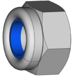
Nyloc-NutA compound object is more than just a union of shapes. For one thing, it needs to allow shapes with different properties, such as a steel nut with a plastic insert (a “Nyloc” nut).

I need to look more closely at DeepSOIC’s Non-PartDesign Body container proposal which looks like it is on the right track for this.

Cloning

I want to design a shape and then insert more than one copy of it. Each wooden shelf of my boot rack is made of three or five parallel strips, which I model as cuboids initially. Later I decide to smooth their upper edges. To do this, I want all the strips to be based on a single template, and I want to modify that template so that the upper two corners are rounded. I don’t want to have to manually select each of the 52 individual edges in turn in order to apply a 4 mm radius.

Basic repetition like this requires the ability to clone a compound object. FreeCAD has the “Part Clone” operation which does this. However, a complication arises when I later modify the original. Many modifications, e.g. “fillet”, are done by wrapping the object with a transformed version of itself. The clones remain clones of the original object and so don’t reflect that modification. One existing way to overcome this is to wrap the object in a container such as “PartDesign Body” (though it has restrictions) and clone the container; then the fillet can be made inside the container and so is reflected by the clones. Another possible design could be that the “Fillet” tool offers to update the clones to point to the new Fillet object instead of the original if the user so chooses.

We need to think clearly about the notion of “the original”. If my table has four legs, I might designate one as the original and the other three as clones. Then if I want to modify them all in the same way I need to easily find the original, and make changes to it in such a way that the changes are reflected in the clones. Alternatively I could make an abstract (hidden) original, and make four clones of that. The abstract, hidden “original” might then be called a template. If I want to make a unique modification on each leg, this approach might be easier to work with, because the difference between the template and the first leg is completely clear, and I can easily choose whether I’m making a change to the template or to a particular instance.

One aspect to using clones is the importance of a local coordinate system that is used in the definition of the original object, since the cloned instances will be placed at different positions within the global coordinate system.

Lattices

Going beyond manually placed clones, it is useful to be able to place a regular array or grid or lattice of clones. FreeCAD provides a simple and very limited array operation.

I am pleased to see that DeepSOIC has been working on a Lattice Workbench for FreeCAD. This looks like it is done the Right Way, a vast improvement over the simple array operation.

We could say that using lattices is somewhat analogous to looping in a sequential programming language: for x in 0, 1, 2, 3: for z in 0, 1, 2: shelf(x * 900, y=0, z * 450 + 100);

Parametric Templates

Notice how a CAD program will usually assume that several simple shapes such as a cuboid and a cylinder are fundamental building blocks, and provide parametric templates for them. That is to say, if I use the provided cuboid tool instead of building one out of six separate faces, then FreeCAD will ensure all the angles remain right angles while allowing me to adjust the length and width and height.

That is all very well but the same principle must also be available for more complex shapes. The width of some strips of my shelves is different from others, so I want the template to be parametric. In this case:

  • a roughly cuboidal shape
  • 18 mm thick
  • variable width and length
  • two of the edges are rounded to a 4 mm radius

And then I want to place one instance at x=0, y=0 with length=900, width=46; and another instance at x=0, y=60 with length=900, width=80; and so on.

The width and length are parameters to be specified on each instantiation (in addition to the placement): that is what makes this a parametric template.

So I need my CAD software to let me define parametric templates for all the shapes I want to use. That is analogous to writing a function in structured programming, and calling the function several times with different parameters.

  • Is there a different professional terminology for what I’m calling “parametric templates” here?

Part Library

A Part Library facility will make it easy to manage templates: to organize and refer to the templates within one model, and to import parts into the model from a shared library of parts, and to create such a library.

  • There is a project called FreeCAD-library. It provides some shapes that may be copied. They are not “parametric templates” in the sense above — for example. There are no associated software enhancements to help with using them.

Refactoring

It must be easy to redefine the way the model is built while preserving the same result.

By refactoring, I mean the ability to replace one definition of an object (or any kind of data in the model) with another definition that produces the same or a similar result. If any other node in the model depended on the node that implemented the old definition, it shall henceforth depend instead on the new one.

Examples:

  • exchange the order of commutative transforms: e.g. change an array of unions to a union of arrays
  • move/rotate/scale a local coordinate system: apply the opposite transformation to the placement of each instance so there is no net change
  • a template specifies the material “wood”; change the template to not specify a material, and change all instances that didn’t override it to specify material “wood”
  • replace a stored transform with its current result (additional possibilities: freeze its result & inactivate but remember the transform; freeze the result & ensure the transform continues to give that result)
  • replace a 2D object with a sketch of itself, or vice versa
  • break any predefined object into its primitive parts along with the relevant constraints
  • replace constraints with equivalent ones: e.g. length & two angle constraints with two length constraints and one angle, defining a triangle

For any refactoring, the opposite refactoring should be available too, to the greatest extent possible.

Extrusion: 2D Sketches and 1D Profiles

Making a 2D sketch and extruding it along the third dimension is a powerful and convenient way of designing 3D shapes. In FreeCAD the Sketcher provides parametric or “constraint-based” 2D drawing that can be used as the basis for extrusion, as an alternative to using a normal 2D shape. (Indeed, the documentation suggests the Sketcher was only intended to be used for this purpose.)

Extruding a 2D face in FreeCAD makes a single solid of uniform thickness. I want a more general extrusion in which the 1D thickness profile is analogous to the 2D profile. I want to extrude my sketch not just in a single homogeneous span but in several segments (example: z=0 to 6 mm; gap; z=12 to 18 mm) to create several solid layers with or without gaps between them.

I want to store a 2D sketch as a template and use it in multiple places with different 1D extrusion profiles. I want to store a 1D extrusion profile as a template and use it in multiple places with different 2D sketches. An extrusion profile can thus serve as a specification for a composite sheet material.

A 1D profile should be able to be parametric (constraint-based), just as a 2D sketch can.

I want to be able to attach properties such as material and colour to the faces in my 2D sketch, and also to the segments in my 1D profile (z=0 to 6 material=plywood; gap; z=12 to 18 material unspecified).

Property specifications should be defaultable (“if not already specified then this”) and overrideable, so that I can choose to specify the material either in the 1D extrusion or in the 2D sketch or by a more complex combination of both.

  • 2D sketch — specifies 2D faces
  • 1D profile — specifies 1D segments
  • both can be parametric (constraint-based)
  • both can be multi-segment

Stored vs. Immediate Transforms

Mirroring, rotation, array — these are parametric ways of defining one part of the model in terms of a transformation of another part.

When a transformation is stored as a transform operator node in the model, then the parameters defining the transform (axis for mirroring, centre and angle(s) for rotation, etc.) can be changed later and the resulting object will be recalculated, or the base object can be changed later and the resulting object will be recalculated to reflect that base object. I will call this way of modelling the stored parametric transform.

The other possibility when applying a transform operator is to store only the resulting object and not the transform that was used. I’ll call that the immediate way of applying a transform.

Both behaviours are useful and both should be available for every kind of transform. The most likely wanted behaviour may well vary depending on the operator and other factors, but what we don’t want is an arbitrary mixture of behaviours, some operators creating a stored transform and others applying their effect immediately.

In FreeCAD today there does seem to be an arbitrary mixture.

In my ideal CAD program there would be a UI to change any operation from parametric to empirical, by removing the transform operator from the model and placing the result instead. This is somewhat analogous to removing a constraint: afterwards, modifying the base object will no longer affect the object created by the transform.

A more advanced UI should also provide ways to convert from empirical to parametric. This is tricky: if B is supposed to be a transformed version of A, then does B in fact differ from A only in respect of one simple transform? Should the UI try to guess the transform or must the user specify it? What if B differs arbitrarily from A? How do we even compare the objects objectively (given they may look the same but be constructed differently, for instance)?

Uniform Hierarchical Modelling

We need to be able to build any further geometry on any calculated geometry. For example, after extruding a flat face to produce a polyhedron, it must then be possible to use any face of that calculated polyhedron as the base for a further extrusion. To achieve this, every calculated result should be presented in the model as standard geometry and not only as a special kind of object whose result doesn’t act like standard geometry.

Requirements:

  • standard objects are composed of standard geometry
    • when I use the built in Rectangle tool, I can select two of its edges and build further geometry on them
  • transform result is standard geometry
    • when the result of a transform operator is a rectangle, I can select two of its edges and build further geometry on them
  • sketch result is standard geometry plus constraints
    • I can build further on two lines of a sketch

It should always be possible to:

  • transform an object in place: that is, replace it with a transformed version of itself, either a stored transform or an immediately applied transform
  • replace an object with a transformed version of another (especially interesting when the result is similar to the old object)

FreeCAD needs…

Here are my thoughts on the most important things that FreeCAD needs if it is to become my ideal CAD system.

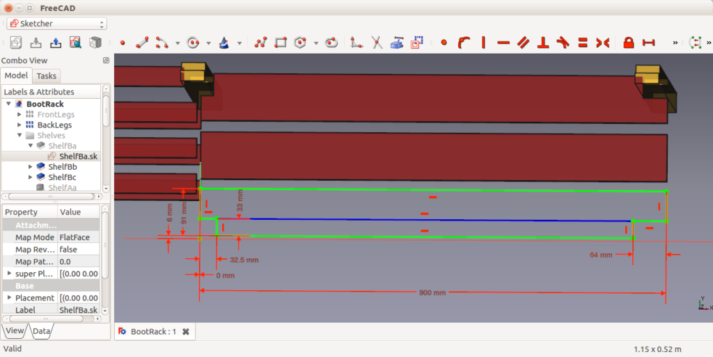
I first used FreeCAD in 2015 to record the detailed dimensions of some rooms in my house and in 2016 to model a boot rack I was building out of wood. The ideas in this article are about fundamental aspects of FreeCAD’s scope and goals, and are based on a background of thinking about CAD as a software developer and hobbyist, as well as my experience using FreeCAD.

I am not talking here about the kinds of user interface features or specific modelling capabilities that are usually entered in a bug tracker as enhancement requests. I mention some ideas of that kind in FreeCAD Usability Improvements.

FreeCAD Needs

Fundamentally:

Every good piece of software that supports complex editing should have:

Interesting bonus capabilities:

  • shared editing

Ethos, paradigms, capabilities and limits of modelling in FreeCAD

In trying to understand how best to use FreeCAD for what I want to do — recording some dimensions and details of rooms in my house; modelling a wooden boot rack that I was making — I was unable to find a lot of the information I wanted. In trying to understand where the developers of FreeCAD are planning to get to eventually, and to decide whether I could hope to contribute to making FreeCAD into my ideal CAD system, I wanted to know more or less the same things. A discussion of the following topics would greatly help.

  • compare with other modelling systems, especially Blender and AutoCAD
  • what can a FC file contain? a single 3D scene? with a single view (camera position and type)? with lighting, background, and other scene rendering metadata? plus zero or more 2D drawings?
  • a scene is composed of what classes of object — CSG objects and mesh objects? can plug-in modules define new types of object?
  • what kinds of object can be combined with or converted to other kinds? what groups of operation can be used on what kinds of object? is there a group of operations that work on every kind of object?
  • to what extent are surface or solid properties supported (colour, texture, stiffness, …)? can arbitrary additional properties be attached to the model even though FreeCAD does not know how to interpret them unless a plug-in extension is loaded?
  • is there any kind of animation support or are we always building a static model?

It is important to describe the goals and aspirations as well as what has already been developed.

A “structured programming” style of modelling

Summary:

I want my CAD software to remember how my model is constructed. If a shape is repeated in three places, I want to be able to modify that shape in one place and have the change propagated to all three places at once. If a face is rectangular, I want to know that its edges will remain parallel when I adjust its width. If each shelf in my boot rack is 18 mm thick, I want its thickness to stay at 18 mm and not reduce by 10% when I decrease the overall height of the rack from 1000 to 900 mm.

For me the ability to use structured design techniques is a key requirement for computer-aided design.

Some important structural modelling requirements are:

  • compound objects
  • cloning
  • parametric templates
  • refactoring
  • extrusion: 2D sketches and 1D profiles

Main article: FreeCAD: Structured CAD

Shared Editing

FreeCAD would be much more powerful with shared editing: the ability to edit and display a model that’s simultaneously being edited and/or displayed by another application. Examples:

  • using Blender to edit a mesh-based subset of the model, while using FreeCAD to display the whole model and edit the rest of it
  • two people simultaneously editing the same shared model, both using FreeCAD

It’s not so much that shared editing is the killer feature, but rather I think that supporting the capability would open the way for some interesting developments such as using an external editor for some tasks (e.g. Blender for editing a mesh) and so freeing FreeCAD from the unattainable goal of having to be a good at everything. Blender will always be better for mesh editing so instead of forever trying to catch up and yet forever remaining a poor substitute, why not harness the power of Blender itself for that task and concentrate more of the FreeCAD development effort on doing the fundamental CAD tasks well?

Shared editing would require a particular kind of software architecture which, if FreeCAD isn’t already designed in the right sort of way, would probably require such major changes that it wouldn’t be feasible. However, from what I’ve seen so far, it looks like FreeCAD’s architecture might be not too far off what’s needed.

FreeCAD: Undo

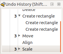
Like any complex editing software, FreeCAD needs a good Undo system. It needs to be reliable: for example, undo followed by redo should always return to exactly the same state. And it needs to be friendly: for example, if I make a succession of tweaks to the view direction without any intervening actions, it should bunch those together as a single change.

A good Undo system

  • must be robust and reliable
    • implemented at the model database transaction level, and not rely on correctly implementing each modification function
    • the implementation of a modification function should only define how many undo steps are stored for this modification (often just one), the scope of each step, and a description of each step
    • getting this wrong should only affect how many undo steps are stored for that modification, and must not affect overall correctness and ability to undo the change
    • undo then redo, or redo then undo, should always leave the model and view exactly as it was
    • undo then redo, or redo then undo, should leave most of the state of the GUI as it was, with few exceptions
  • should show clearly and definitely that undo really has returned to the prior state
    • after undoing everything since the last save, file “modified” indicator should return to “unmodified” and exit should not prompt to save changes
  • should distinguish changes to the model itself from other state changes (e.g. to the view) so it is possible to make two separate UI functions:
    • undo the last change to the overall state (whether that was a change of model or of view or of both)
    • undo the last change to the model itself (either also undoing all view changes made since then, or keeping the view as it is)
  • should use appropriate granularity
    • a series of changes to the view should be grouped together
    • a series of changes to one parameter (e.g. width of a particular rectangle) should be grouped as a single change: the main reason is it is common to make a series of increments and decrements before deciding on the correct result, especially if using the scroll wheel; a related concern is entering a number such as 123 into some UI widgets causes a change first to 1, then to 12, then to 123
    • bigger granularity is often appropriate: for example, creating a new cuboid at a default size followed by adjusting all its dimensions could be grouped as a single change
  • should provide an Undo History list

I am pleased to read that wmayer has recently done some work on improving undo/redo in FreeCAD.

FreeCAD Usability Improvements

Some of my ideas for usability improvements in FreeCAD.

Visual feedback

Such as…

  • continuous immediate previewing of all changes
    • abolish all those Wizard-style input screens that force the user to enter the centre of the circle first, and then its radius, and then its plane of orientation: let the user freely specify and adjust all the parameters in whatever order makes most sense to them in that particular instance
  • better visibility controls on the model hierarchy
    • distinguish “this polygon is hidden because I temporarily want to see what’s behind it” from “this polygon is hidden because it is not itself a surface of the final 3D model: it is only the input data for an extrusion”
    • provide a way to temporarily hide a whole group and later return its visibility to the previous state in which some members of the group were visible and others were hidden
  • describe the selection in words in the status bar
    • Inkscape does this very well: e.g. “5 objects selected of types Rectangle, Path”
  • show the current selection
    • including selected elements whose visibility is set to “hidden”
    • including selected elements that would otherwise be hidden behind solid-rendered elements that are nearer the viewer
  • say what Undo and Redo will do
    • e.g. “Undo: Create Rectangle”
  • indicate whether the file is modified and whether the model is modified
    • two separate things, as the file includes both the model and the view settings

Sketcher

  • while editing a sketch mapped to a face, show that face as external geometry (to be used as construction lines) [did I notice something like this is now done?]
  • while editing, ensure the sketch is visible (e.g. by automatically fading everything else)
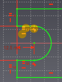
  • don’t clutter the display with tiny details: when the displayed size of an element is small, hide the associated constraint symbols

Constraints UI (FreeCAD)

Ideas for improving the constraints UI in FreeCAD. These are some ideas that I have been thinking about since I first used FreeCAD in 2015.

It is lovely feature of FreeCAD that you can create a 2D drawing by the use of constraints — specifying geometry in terms of relationships such as “line A must be horizontal, the same length as line B, and tangential to arc C”. However, in FreeCAD at the moment this feature is confined to the Sketcher and segregated from the standard drawing tools such as those in the Draft workbench.

I’d like constraints to be available much more generally. On the FreeCAD discussion forum I asked last year if anyone has any grand plans and DanielC asked recently why Draft and Sketcher are separate. I have some ideas about how I think CAD should work, with and without constraints. I decided to expand on my ideas in writing in order to share them and improve them based on other people’s ideas. Maybe I will eventually turn the ideas into working code, or maybe someone else will.

Sketching a Face

The Sketcher documentation says a sketch is intended to be used to draw a single face, perhaps with holes in it, or alternatively to draw a set of features (pockets or pads) on an existing face. This means the sketch should consist of one or more closed and non-intersecting outlines. The Sketcher user interface currently provides no assistance with keeping to this rule: it allows freely scattering any set of disjoint and intersecting lines and even isolated points. Blender, by contrast, features a user interface in which the user can build a complex shape by starting with a simple shape and successively modifying it, at all times choosing actions that maintain the closed shape, never creating arbitrary disconnected or intersecting edges. This style can be seen in Yorik’s Blender tutorial where in step 4 he starts with a small square and by extending it in various ways creates a complex floor plan. That user interface is explicitly modelling a face, whereas Sketcher draws a line drawing which is only implicitly to be thought of as representing a face.

Sketching a face is an important task, and it makes sense to have a user interface that explicitly supports this task. Such a UI would explicitly support drawing a face, by ensuring its boundary line (and those of any holes) remains closed and non-intersecting. It would indicate which area is inside and which is outside, by colouring the area of the face. It would provide more tools which modify the shape of the face directly while keeping it a valid face, like the Blender tools mentioned above, such as the (already existing) fillet tool. It would still support arbitrary lines and points as construction geometry.

Real Physical Shapes

A basic concept is that we usually want to model a real physical shape rather than an abstract mathematical kind of geometry. Regardless whether we are drawing the outline of a single face or a much more general drawing, this has at least two consequences. As a user I expect the sign or handedness of dimensions to be preserved: the right-angle at a convex corner is not the same as the right-angle at a concave corner. And a real object has a non-zero size.

Elements (except points) have non-zero size. Examples:

  • line length != 0 (else degenerate to a point)
  • circle/arc radius != 0 (else degenerate to a point)
  • arc angle != 0 (else degenerate to a point)

Dimension constraints are “signed” and angles are “handed”: there is no ambiguity between positive and negative or left and right. (Failure to apply this principle has led to the “Flipping Problem” documented in this Sketcher tutorial, which has plagued FreeCAD for a long time.)

Signed distance:

  • x-position, y-position
  • x-distance, y-distance
  • point-to-line distance (sign indicates which side of the line the point is on, relative to the line direction)
  • parallel-lines distance (sign indicates which side the second line is on, relative to the first line’s direction)

Signed (or “handed”) angle, with range of a full 360°:

  • absolute orientation
  • arc start and end angles
  • relative angle

Some dimensions are unsigned (just a magnitude):

  • point-to-point distance
  • line length
  • circle/arc radius

Some apparently dimensionless constraints are effectively a signed value, although the magnitude is implied and only the sign is apparent to the user. (See Zero or Special Value Constraints below.) Examples:

  • horizontal, vertical line (sign indicates direction)
  • parallel, tangent (sign indicates relative directions)
  • perpendicular (sign indicates handedness relative to the two directions)

Solving the Flipping Problem

In 2015 I wrote a patch to test the idea of making the constraints signed or handed. To make it simple I implemented all the angle-related constraints, including special cases such as “horizontal” and “vertical”, in terms of the same basic numeric angle constraint code, removing all the optimized implementations of the special cases. The result seemed to robustly preserve topology, exhibiting no flipping.

I didn’t finish it or contribute it back to the project yet. I ought to at least put it in GitHub. Here it is as a patch:

2015-solve-flipping-1.patch

Zero or Special Value Constraints

Some common constraints can be defined as a user-interface alias for a certain value of a dimension constraint. Examples:

  • Coincident <-> point-to-point distance or H- and V-distances = 0
  • Point-On-Line <-> point-to-line distance = 0
  • H-align, V-align <-> V-, H-distance = 0
  • Horizontal, Vertical <-> absolute orientation = 0°, 180°, ±90°
  • Parallel, Perpendicular <-> relative angle = 0°, 180°, ±90°

The system need not remember whether the user entered a zero dimension as numeric zero or by its special name, and the user interface should always show the special name in preference to numeric zero.

The system may prefer to implement each special value constraint either using the general dimension implementation with a value of zero or using a special-case implementation. For example, some comments in the forums indicate that FreeCAD’s constraint solver works well only when the special-case implementations are used.

Basic Constraint Types

A fairly complete set of the most basic constraint types, including both dimensioned forms and zero or special value forms where possible. Note that the current Sketcher UI does not include line-to-line distance.

I have changed some of the icons, such as absolute angle, to better indicate their specific meaning; I would also like to change those for absolute h- and v-position.

Length and Distance

32px-Constraint_Length 32px-Constraint_Radius point-to-point distance / radius

32px-Constraint_HorizontalDistance 32px-Constraint_VerticalDistance absolute h- / v- / h- and v-position

32px-Constraint_HorizontalDistance 32px-Constraint_VerticalDistance h- / v-distance

32px-Constraint_PointOnPointcoincident (point-to-point or h- and v- distance = 0)

point-to-line distance

32px-Constraint_PointOnObject point on line (point-to-line distance = 0)

Constraint_Line_Line_Distance_1 line-to-line distance

32px-Constraint_Tangent tangent (line-to-line distance = 0)

Orientation and Angle

Constraint_AbsoluteAngle_1 absolute angle (orientation)

32px-Constraint_Horizontal 32px-Constraint_Vertical horizontal (abs. angle = 0° or 180°) / vertical (90° or -90°)

relative angle

32px-Constraint_Parallel 32px-Constraint_Perpendicular parallel (rel. angle = 0° or 180°) / perpendicular (90° or -90°)

Basic Relationships

32px-Constraint_EqualLength equal dimension

Complex Relationships

Some examples of more complex relationships. I would not consider these to be basic constraints.

32px-Constraint_Symmetric symmetry around a point (h- and v-distances negative of the other) or line (h- and v-distances related to the other)

32px-Constraint_SnellsLaw Snell’s law relating two angles

Constraint_Parallel_Distance Parallel at a distance (combination of parallel and line-to-line distance)

[-·-] Tangent continuation (combination of tangent and coincident)

User Interface

  • When editing a constraint of a type which has both a dimensioned form and a zero form (e.g. Point Distance From Line and Point On Line), provide an option to switch it to the other form.

Snapping is Constraint (FreeCAD)

Thinking about the Sketcher UI in FreeCAD

Snapping is Temporary Constraint

Sketcher Constraints help us to position a new point coincident with an existing point, or to set the angle of a new line parallel with an existing line, and so on. This relationship is stored, and the actual position is calculated from the relationship.

Draft Snap also helps us to position a new point coincident with an existing point, or to set the angle of a new line parallel with an existing line, and so on. However, only the new position is stored; the fact that this position was determined by a relationship with another object is immediately forgotten.

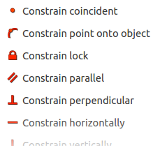
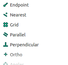
Notice that there is a lot of overlap in the available kinds of Sketcher constraint and the available kinds of Draft Snap. There are snaps that correspond more or less closely with each kind of constraint, and vice-versa. That should not be surprising.

Coincident 32px-Constraint_PointOnPoint <-> 32px-Snap_Endpoint 32px-Snap_Midpoint 32px-Snap_Center Endpoint / Midpoint / Centre

Point on line 32px-Constraint_PointOnObject <-> 32px-Snap_Near 32px-Snap_Extension Nearest / Extension

Lock X and Y 32px-Sketcher_ConstrainLock <-> 32px-Snap_Grid Grid intersection

Horizontal / Vertical 32px-Constraint_Horizontal 32px-Constraint_Vertical <-> 32px-Snap_Ortho Orthogonal

Parallel / Perpendicular 32px-Constraint_Parallel 32px-Constraint_Perpendicular <-> 32px-Snap_Parallel 32px-Snap_Perpendicular Parallel / Perpendicular

Both Snapping and Constraints have the same purpose: to determine the placement (position and/or orientation) of an object in terms of a relationship with either another object or the world coordinate system. The difference is that a constraint is stored in terms of its definition, whereas with snapping only the resulting placement is stored.

Snapping implies that there is some significant feature to snap to, and that the user wants the new object to have this relationship to that existing feature. A useful, intuitive behaviour would be:

  • snapping is available for every kind of constraint that relates to existing geometry
  • snapping always produces a stored constraint (if the user wants it)

In Sketcher there is an auto-constraint option that produces a stored constraint automatically for some kinds of constraint, including coincident point, point on line, tangent, horizontal, vertical; but not parallel, perpendicular, equal length, etc. One or more icons appear near the cursor to indicate what kind of constraint will be produced.

Sketcher also performs some limited snapping (to a point and to a grid intersection only, AFAICT). Like with Draft Snap, it just stores the resulting position (with no constraints applied) when snapping takes place and auto-constraint is not enabled.

For the record, a couple more features are closely related to constraints:

  • temporarily constraining movement to an axis during an operation such as Move is much the same thing as snapping, and likewise should generate a stored constraint
  • a Draft Dimension is similar to a non-driving constraint

How It Should Work

This is what I’d like to have.

  • Draft and Sketcher should both support snapping in the same way and with all the types of snap;
  • every type of snap should be able to produce a (stored) constraint in Sketcher;
  • consistent naming and icons between snapping and constraints, and between Draft and Sketcher;
  • consistency between Draft Dimensions and Sketcher Dimension Constraints (both driving and non-driving).

Snapping should be an easy, fast and intuitive method of entering most constraints.


hCard versus Gravatar

My ‘avatar’ is a small image of my face that is shown next to comments that I made, to identify me, on this blog and on many social networks.

Gravatar Gravatar

I uploaded my avatar to Gravatar.com which is a service that stores the avatars of millions of people and provides them to any social media web sites that want to display them. The main reason to use Gravatar is that whenever I want to update my image, I only need to do so once, in this one place, rather than updating it on the configuration pages of every social networking system I use.

My blog, running the WordPress.org software, is one of the many systems that fetches my avatar from Gravatar. In fact WordPress, by default, seems to only allow me to use Gravatar and not even to provide an option to host my own image directly.

But why should I use a third-party service? I want to host my personal identification at my own domain.

hCard microformat microformats

There’s already an Open protocol for publishing an identifying image of myself: the hCard microformat and specifically its “photo” property*. That’s more or less the same thing as an avatar. Gravatar even provides a user’s profile data as an hCard, including their avatar, as well as providing the avatar through its own Gravatar Image Requests protocol.

Anyone can implement hCard on their own domain just by inserting some static HTML markup. I’ve done it on my own site.

So if I have my domain why should I use Gravatar rather than hosting my own hCard?

Thoughts

  • If the Gravatar Image Requests protocol is much more useful than just serving a single static image, then my domain could host a service serving my own avatar through the Gravatar protocol. Instead of popular web sites assuming that they will fetch my avatar from (conceptually) www.gravatar.com/avatar/<me@my-domain> they should then fetch it in the same way but from an address like <my-domain>/avatar/<me>.
  • Any self-hosted software, such as WordPress.org, that can fetch my avatar from Gravatar should also offer the option of fetching it directly from my domain, in order to not force me to use a particular third-party service.
  • Although it would be nice, I wouldn’t expect a silo system to offer that option. They surely gain advantages such as efficiency by using a single third-party system to provide the avatars of all their users. However, Gravatar could offer the option to act as a proxy server for my own domain.

Can we design a system that retains any significant benefits of the Gravatar system while allowing me to host my data myself?

Is there at least a WordPress plug-in that provides something towards this?

Would parts of Gravatar’s protocol be a useful complement to the hCard protocol capabilities?


  • There is also an hCard “logo” property. There is also h-card, the microformats2 successor to hCard, with corresponding “u-photo” and “u-logo” properties.


LyX – semantic editing

I want to like LyX: it has the right attitude, saying don’t bother me with choosing a font style and size, concentrate on the meaning of what I’m writing.

Reading an introduction to it (years ago), I quickly came up against this nugget (paraphrased):

To emphasise text, don’t mark it “italic”. The LyX way is to mark it with “emphasis”. The default rendering of “emphasis” is italic.

So far so good, if emphasis is what I want.

Let’s say I’m writing about part names and project names and I want to make those terms stand out like I’ve done here — partly to emphasise them, I suppose, but also to group related terms together, and potentially later on I may want to distinguish the part names from the product names by displaying them in different ways. I don’t just want these terms lumped together with ever other phrase that’s emphasized.

How do I define and apply the new semantic mark-up for “part name” to the part names (default rendering: italic), and “project name” to the project names (default rendering: also italic)?

Last I looked, LyX didn’t make it easy.

Unfortunately the take-away impression was more like this: for italic, press the “Emphasis” button or Control-E; for bold, press the “Strong” button or Control-S.

The button for applying the style “part name” needs to appear next to those for the predefined styles such as “emphasis”. And when I first decide I want a style for a part name, I need to create this new style very quickly and easily.

Of course I’m not talking only about italics. This attitude should pervade any semantic mark-up software such as LyX.