Ideas for improving the constraints UI in FreeCAD. These are some ideas that I have been thinking about since I first used FreeCAD in 2015.
 It is lovely feature of FreeCAD that you can create a 2D drawing by the use of constraints — specifying geometry in terms of relationships such as “line A must be horizontal, the same length as line B, and tangential to arc C”. However, in FreeCAD at the moment this feature is confined to the Sketcher and segregated from the standard drawing tools such as those in the Draft workbench.
I’d like constraints to be available much more generally. On the FreeCAD discussion forum I asked last year if anyone has any grand plans and DanielC asked recently why Draft and Sketcher are separate. I have some ideas about how I think CAD should work, with and without constraints. I decided to expand on my ideas in writing in order to share them and improve them based on other people’s ideas. Maybe I will eventually turn the ideas into working code, or maybe someone else will.
Sketching a Face
The Sketcher documentation says a sketch is intended to be used to draw a single face, perhaps with holes in it, or alternatively to draw a set of features (pockets or pads) on an existing face. This means the sketch should consist of one or more closed and non-intersecting outlines. The Sketcher user interface currently provides no assistance with keeping to this rule: it allows freely scattering any set of disjoint and intersecting lines and even isolated points. Blender, by contrast, features a user interface in which the user can build a complex shape by starting with a simple shape and successively modifying it, at all times choosing actions that maintain the closed shape, never creating arbitrary disconnected or intersecting edges. This style can be seen in Yorik’s Blender tutorial where in step 4 he starts with a small square and by extending it in various ways creates a complex floor plan. That user interface is explicitly modelling a face, whereas Sketcher draws a line drawing which is only implicitly to be thought of as representing a face.
Sketching a face is an important task, and it makes sense to have a user interface that explicitly supports this task. Such a UI would explicitly support drawing a face, by ensuring its boundary line (and those of any holes) remains closed and non-intersecting. It would indicate which area is inside and which is outside, by colouring the area of the face. It would provide more tools which modify the shape of the face directly while keeping it a valid face, like the Blender tools mentioned above, such as the (already existing) fillet tool. It would still support arbitrary lines and points as construction geometry.
Real Physical Shapes
A basic concept is that we usually want to model a real physical shape rather than an abstract mathematical kind of geometry. Regardless whether we are drawing the outline of a single face or a much more general drawing, this has at least two consequences. As a user I expect the sign or handedness of dimensions to be preserved: the right-angle at a convex corner is not the same as the right-angle at a concave corner. And a real object has a non-zero size.
Elements (except points) have non-zero size. Examples:
- line length != 0 (else degenerate to a point)
- circle/arc radius != 0 (else degenerate to a point)
- arc angle != 0 (else degenerate to a point)
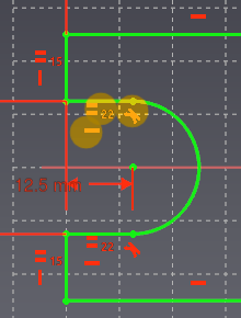
Dimension constraints are “signed” and angles are “handed”: there is no ambiguity between positive and negative or left and right. (Failure to apply this principle has led to the “Flipping Problem” documented in this Sketcher tutorial, which has plagued FreeCAD for a long time.)
Signed distance:
- x-position, y-position
- x-distance, y-distance
- point-to-line distance (sign indicates which side of the line the point is on, relative to the line direction)
- parallel-lines distance (sign indicates which side the second line is on, relative to the first line’s direction)
Signed (or “handed”) angle, with range of a full 360°:
- absolute orientation
- arc start and end angles
- relative angle
Some dimensions are unsigned (just a magnitude):
- point-to-point distance
- line length
- circle/arc radius
Some apparently dimensionless constraints are effectively a signed value, although the magnitude is implied and only the sign is apparent to the user. (See Zero or Special Value Constraints below.) Examples:
- horizontal, vertical line (sign indicates direction)
- parallel, tangent (sign indicates relative directions)
- perpendicular (sign indicates handedness relative to the two directions)
Solving the Flipping Problem
In 2015 I wrote a patch to test the idea of making the constraints signed or handed. To make it simple I implemented all the angle-related constraints, including special cases such as “horizontal” and “vertical”, in terms of the same basic numeric angle constraint code, removing all the optimized implementations of the special cases. The result seemed to robustly preserve topology, exhibiting no flipping.
I didn’t finish it or contribute it back to the project yet. I ought to at least put it in GitHub. Here it is as a patch:
Zero or Special Value Constraints
Some common constraints can be defined as a user-interface alias for a certain value of a dimension constraint. Examples:
- Coincident <-> point-to-point distance or H- and V-distances = 0
- Point-On-Line <-> point-to-line distance = 0
- H-align, V-align <-> V-, H-distance = 0
- Horizontal, Vertical <-> absolute orientation = 0°, 180°, ±90°
- Parallel, Perpendicular <-> relative angle = 0°, 180°, ±90°
The system need not remember whether the user entered a zero dimension as numeric zero or by its special name, and the user interface should always show the special name in preference to numeric zero.
The system may prefer to implement each special value constraint either using the general dimension implementation with a value of zero or using a special-case implementation. For example, some comments in the forums indicate that FreeCAD’s constraint solver works well only when the special-case implementations are used.
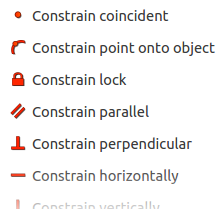
Basic Constraint Types
A fairly complete set of the most basic constraint types, including both dimensioned forms and zero or special value forms where possible. Note that the current Sketcher UI does not include line-to-line distance.
I have changed some of the icons, such as absolute angle, to better indicate their specific meaning; I would also like to change those for absolute h- and v-position.
Length and Distance
![]()
![]() point-to-point distance / radius
point-to-point distance / radius
![]()
![]()
![]() absolute h- / v- / h- and v-position
absolute h- / v- / h- and v-position
![]()
![]() h- / v-distance
h- / v-distance
![]() coincident (point-to-point or h- and v- distance = 0)
coincident (point-to-point or h- and v- distance = 0)
![]() point-to-line distance
point-to-line distance
![]() point on line (point-to-line distance = 0)
point on line (point-to-line distance = 0)
![]() line-to-line distance
line-to-line distance
![]() tangent (line-to-line distance = 0)
tangent (line-to-line distance = 0)
Orientation and Angle
![]() absolute angle (orientation)
absolute angle (orientation)
![]()
![]() horizontal (abs. angle = 0° or 180°) / vertical (90° or -90°)
horizontal (abs. angle = 0° or 180°) / vertical (90° or -90°)
![]() relative angle
relative angle
![]()
![]() parallel (rel. angle = 0° or 180°) / perpendicular (90° or -90°)
parallel (rel. angle = 0° or 180°) / perpendicular (90° or -90°)
Basic Relationships
![]() equal dimension
equal dimension
Complex Relationships
Some examples of more complex relationships. I would not consider these to be basic constraints.
![]() symmetry around a point (h- and v-distances negative of the other) or line (h- and v-distances related to the other)
symmetry around a point (h- and v-distances negative of the other) or line (h- and v-distances related to the other)
![]() Snell’s law relating two angles
Snell’s law relating two angles
![]() Parallel at a distance (combination of parallel and line-to-line distance)
Parallel at a distance (combination of parallel and line-to-line distance)
[-·-] Tangent continuation (combination of tangent and coincident)
User Interface
- When editing a constraint of a type which has both a dimensioned form and a zero form (e.g. Point Distance From Line and Point On Line), provide an option to switch it to the other form.
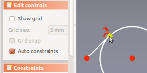 In Sketcher there is an auto-constraint option that produces a stored constraint automatically for some kinds of constraint, including coincident point, point on line, tangent, horizontal, vertical; but not parallel, perpendicular, equal length, etc. One or more icons appear near the cursor to indicate what kind of constraint will be produced.